Markers are of types:
LINE, a 3D multi-point planar lineExample use:
DASH, a 3D two-point line
POLY, a filled planar 3D polygon
CIRCle, a 3D circle
DISC, a 3D disc (filled circle)
TEXT, 3D vector text with selected width and height
RULE, a 3D rule or (ruler) with selected tic spacing
CORNERS
...
PLANES
...
MARKERS ;optional section
;type co-ids RGB-color offset
POLY 1 2 3 4 {173 179 77} 0.0
LINE 1 2 3 4 1 {90 90 90} 0
DASH 11 1 2 {0 90 90} 0.1
POLY 11 12 2 1 {173 179 77} 0.0
CIRC 20 12 13 { 0 0 0} 0.01
0.12
DISC 20 12 13 {200 200 200} 0.01 0.12
RULE 11 12 13 {200 200 200} 0.01 1.0
TEXT 3 2 12 {255 0 0} 0.01 "Wall" 0.04 0.02
Corner id:s given are are used to define a plane that the markers can be offset from or to define the direction of TEXT. For example, the DASH is defined from corner 11 to 1 but it is offset 0.1 m from a wall defined by plane 11 1 2).
Note that also string constants can be used:
LOCAL blue = "{0 0 255}"and CATT-Edit can be used to select and insert the RGB color triplet visually.
...
POLY 1 2 3 4 %blue% 0.0
A geometry can be exported as a Marker-file (. MRK) and such files can then be inserted in another MARKERS section, translated and rotated into the desired position:
LOAD, loading an MRK-fileSample use of this feature is to create e.g. a chair once as an MRK-file and then LOAD one or more instances of the chair into other projects as markers:
MARKERS
LOAD 1 2 3 "chair.MRK"
LOAD 12 23 "chair.MRK"
where bolded corner id:s are used to defined the new coordinate system (to place with z upwards only two id:s are needed).
Marker-files can indirectly be made in AutoCAD via the AutoLISP interface and then modified in GEO-format and exported as a marker-file. A directive NOROOM can be used if a GEO-file is used only to create a Marker-file (no source and receiver files necessary, no calculations made).
Markers can be switched off while editing and displaying a model.
Useful marker objects will gradually become available for download including GEO source for parametrical variation.
Marker-files
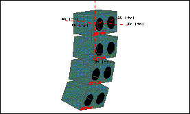
are also used for loudspeaker "visuals".

- TEXT example -

- LOAD example -

- TEXT example -

- TEXT, LOAD, CIRC, DISC, LINE example -

- An MRK-file used for source visuals -

- An MRK-file used for array visuals -