TUCT™ stands for The Universal Cone Tracer
and predicts echograms and
room impulse responses offering several
different internal algorithms depending on the
room case, ranging from basic to advanced. In
particular it offers very good ways to predict and auralize
open cases (outdoor arena etc.) that traditionally often
have necessitated making a faked closed model for most algorithms
to work well, especially for auralization, and cases
where flutter echoes may be important (but also the basic algorithm
will catch flutter echoes). Also prediction and auralization
in big
indoor venues with high absorption will benefit. The core
algorithms are based on geometrical
acoustics (GA) with various levels and combinations
of actual and random
diffuse ray/cone split-up and are general
so that as the algorithms are further refined
and computer speed increases additional levels of
actual split-up can be incorporated.
TUCT™ relies on the geometry
modeling view/check and library
handling (absorption, source directivity, array
modeling, HRTFs, headphones) of the CATT-Acoustic™ main program (CATT-A) that exports
a file (.CAG) containing the
data necessary and runs TUCT™. Everything previously
learned regarding geometry
modeling in CATT-Acoustic™ and old models can thus
be directly used but all prediction and auralization
is from v9 instead performed by TUCT™ in a simpler, more general and more flexible
way.
TUCT™ is a near total rewrite from scratch
but also includes some parts
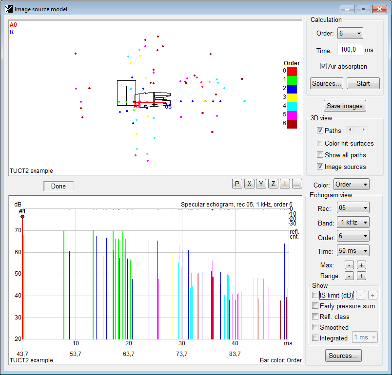
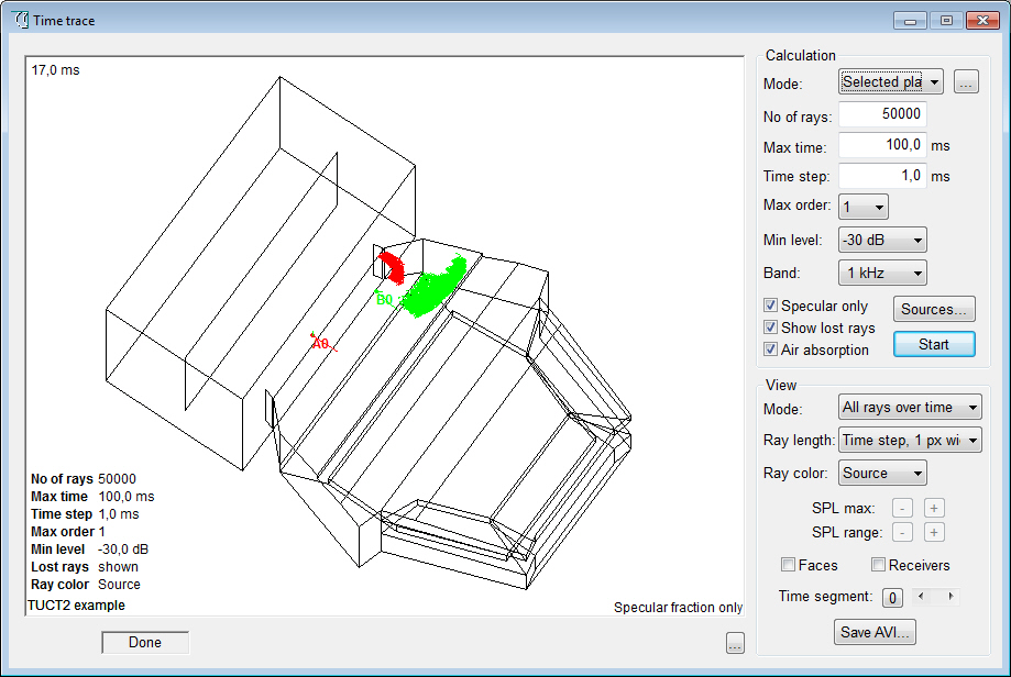
of CATT-Acoustic™ v8 such as Pixel rendering, an Image
source model and Time trace
that are adapted and extended to work with
TUCT™ as separate tools in a more flexible
and integrated way. Most parts
of the CATT-Acoustic™ v8 post-processing have no
direct correspondence in TUCT™, they are simply not needed. The few
remaining, still useful but
not very often used, utilities are kept
in the stripped-down CATT-A v9.
Major differences
between TUCT™ and the previous CATT-Acoustic™ v8 prediction/auralization:
- prediction algorithms
are more general and do not rely
on reflection growth extrapolation like
the RTC
- auralization is based
on the full reverb tail instead
of recreating it in post-processing
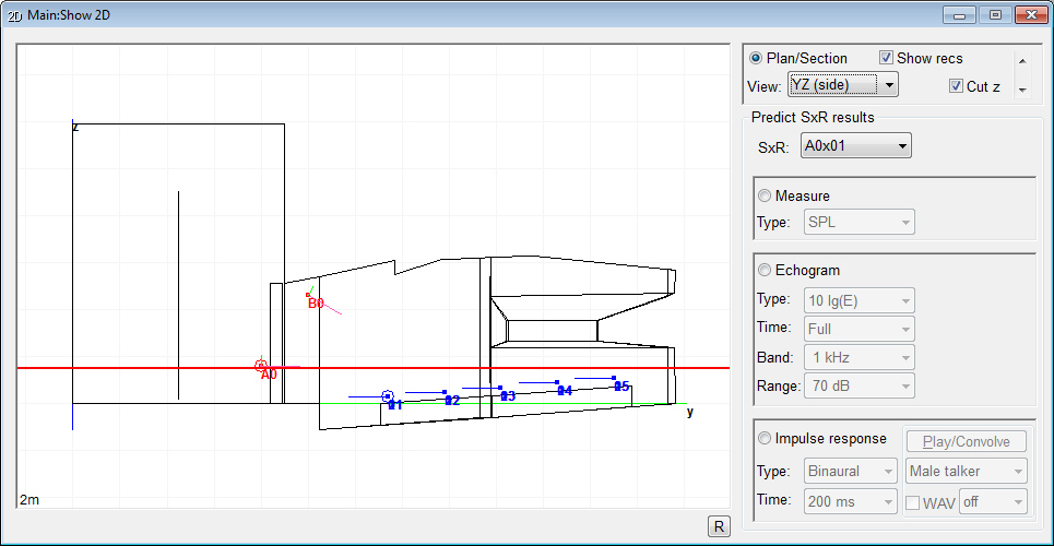
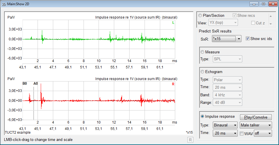
- no separate post-processing
stage for auralization required,
impulse responses are available for evaluation
and convolution/listening directly after prediction
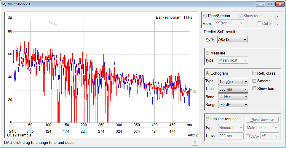
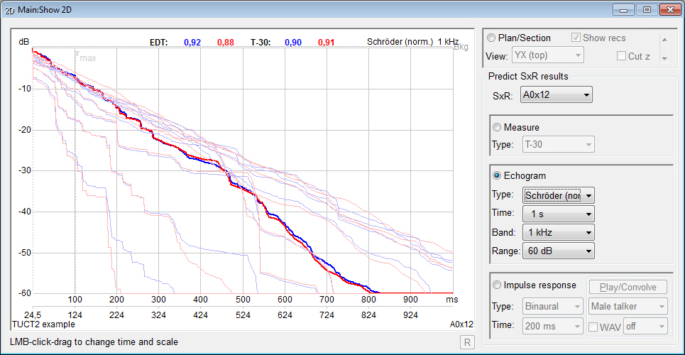
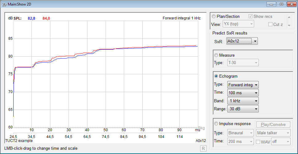
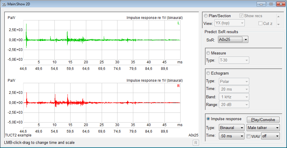
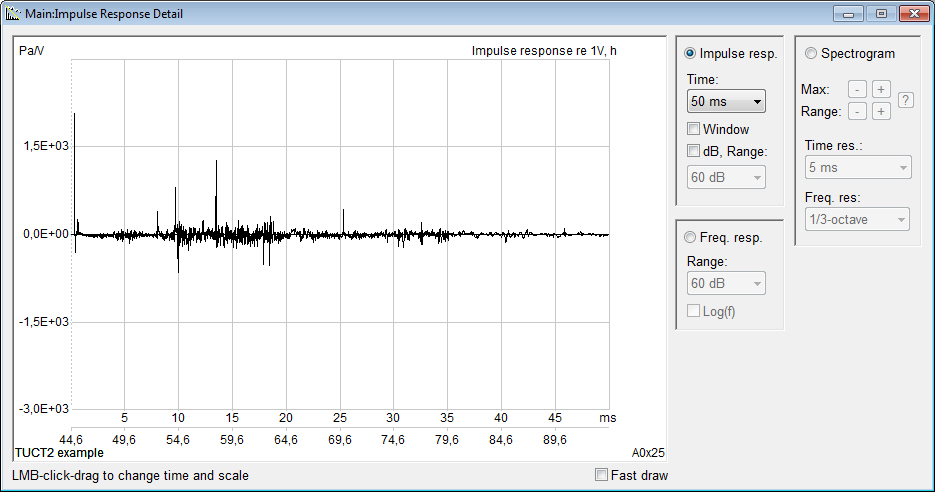
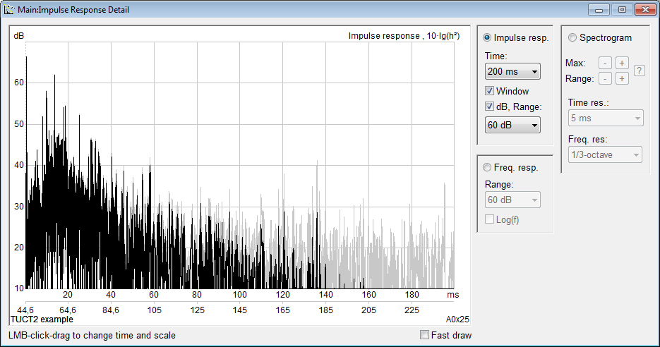
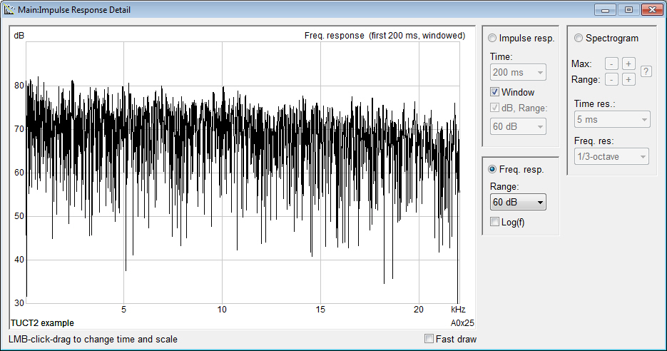
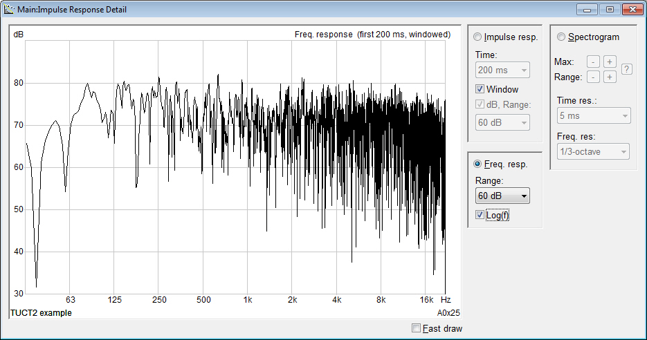
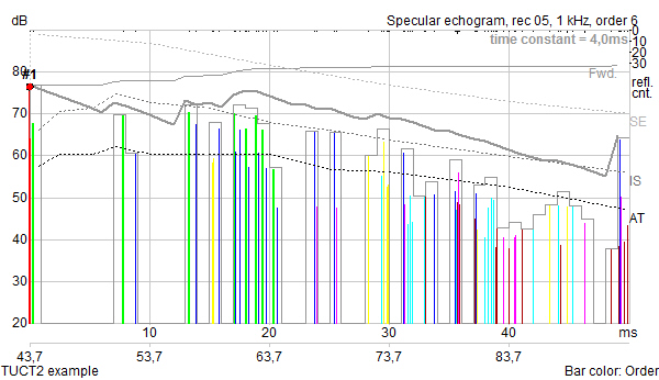
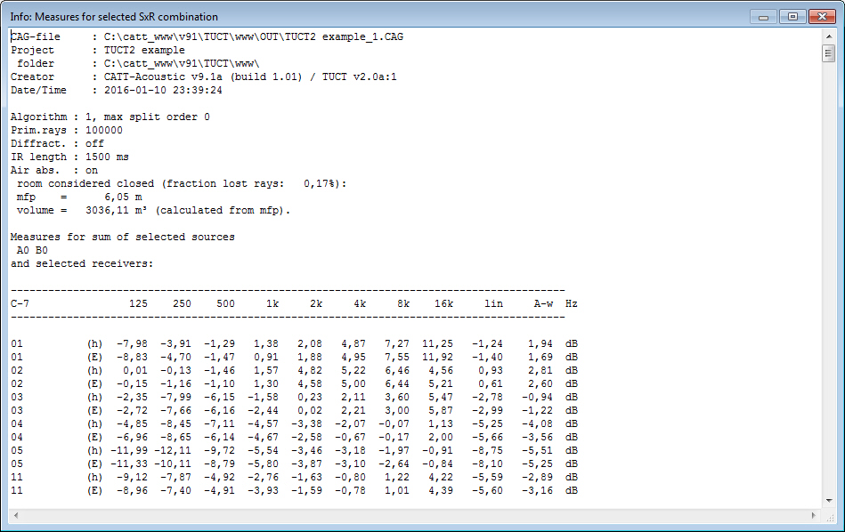
- displays measures
and graphs for both an energy echogram and
a pressure impulse
response giving an indirect
indication about the prediction reliability
at low frequencies
- the
pressure impulse response made it possible to include a comprehensive
treatment of early diffraction using
a secondary edge-source method based on a
discrete Huygens interpretation of Biot-Tolstoy (from v1.1a). This method has few
principle limitations when used in room acoustics
with finite edges, especially as compared to infinite
screen formulas. The documentation includes
a 20+ page whitepaper about how diffraction has been
implemented, and why a screen formula has not been used.
- no separate multiple
source addition or auralization
required, multiple source impulse
responses are available for evaluation
and convolution/listening directly after prediction
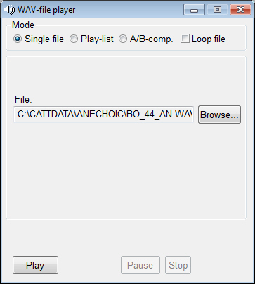
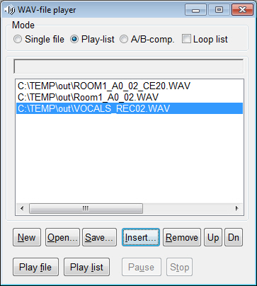
- no separate convolution
utility necessary, just click
Play/Convolve for immediate listening,
even for multiple sources like in a PA system
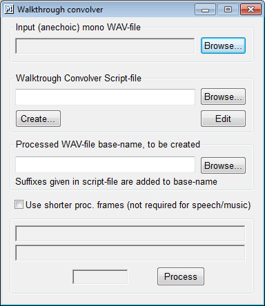
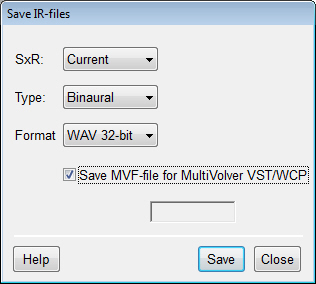
- for multiple source
(with different sounds) auralization
MultiVolver VST™ and MultiVolver WCP™ (off-line version) can
be used, TUCT saves
settings-file for easy integration
- no separate relative
calibration required to auralize
positions within a room with relative
levels preserved
- can run in multiple
instances (examples: one instance
can perform an audience area mapping while
another performs impulse response prediction for the
same model, or one instance predicts one room and
a second instance another room while a third is used
to view old results)
- uses multiple
processor cores for all major processing functions,
number of threads automatically selected or specified
- many types of calculation
results can be viewed in parallel
(it can e .g. be useful to view the results
of an early part Image source model together with
the results of a full calculation to identify main early
reflections)
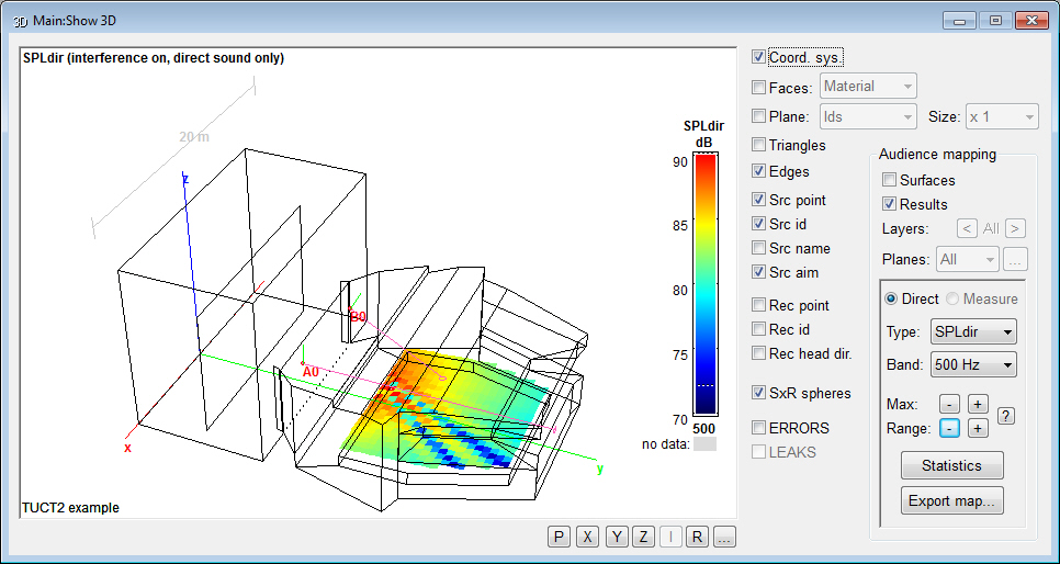
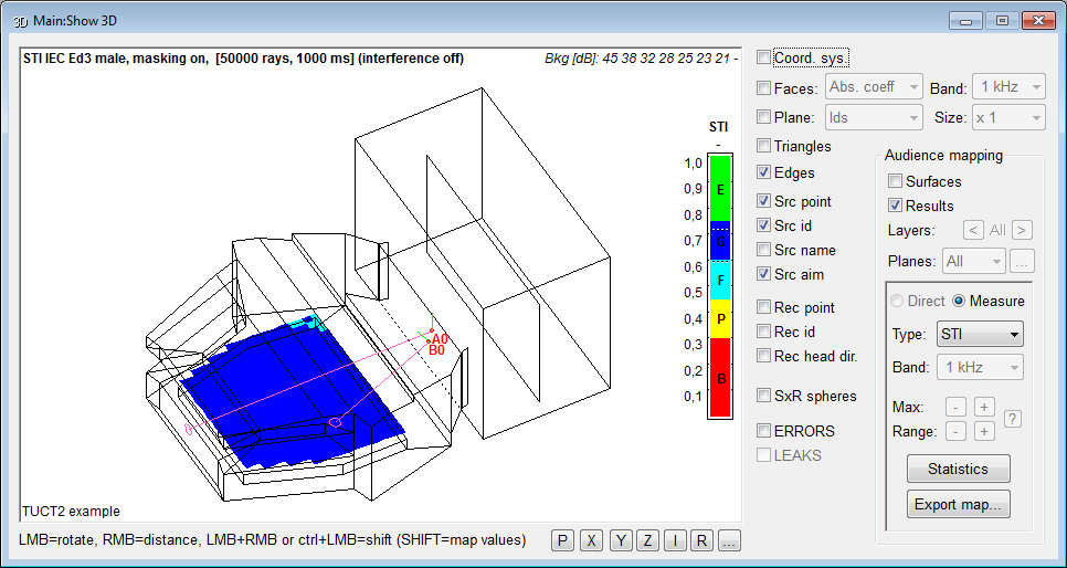
- direct or reflected
sound can be mapped on all walls and/or audience surfaces at an interactively selected
resolution via the new Surface
rendering (similar to Pixel rendering
but at a variable absolute spatial resolution allowing
free model rotation and rescaling)
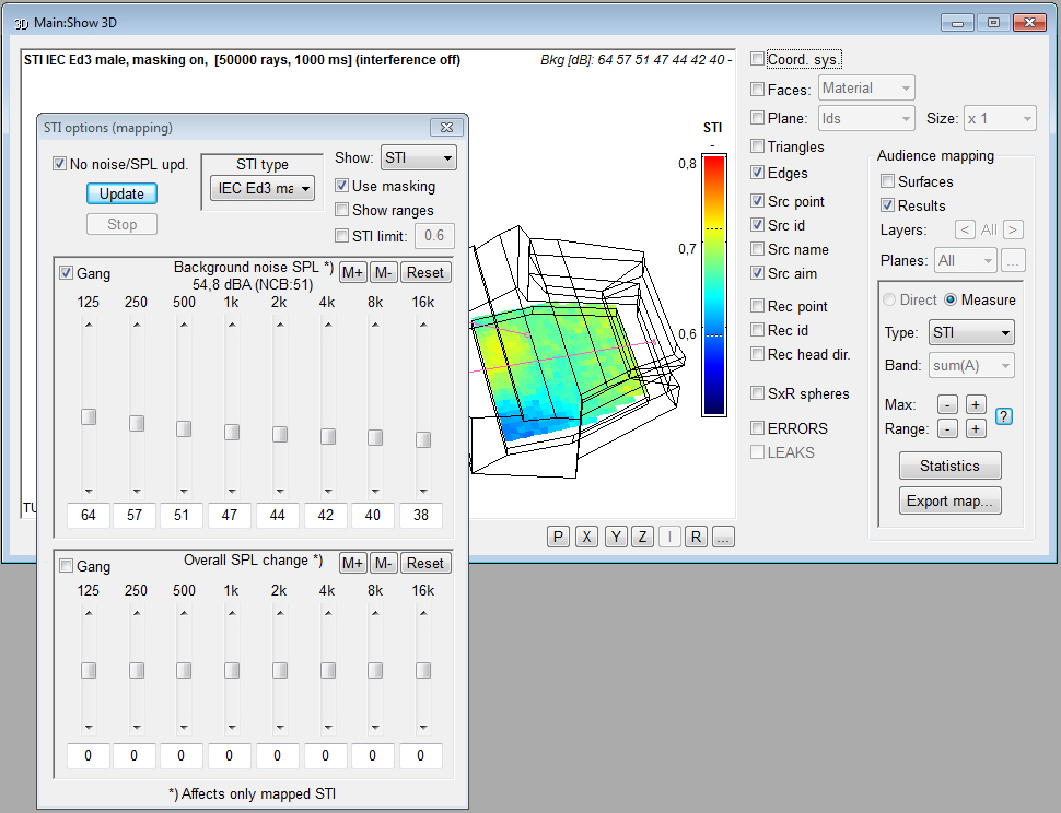
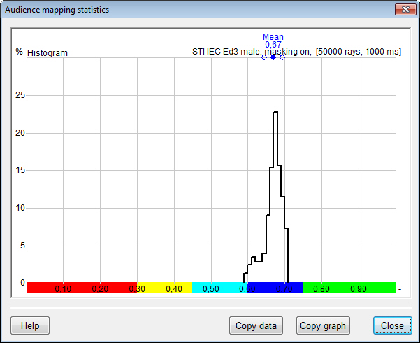
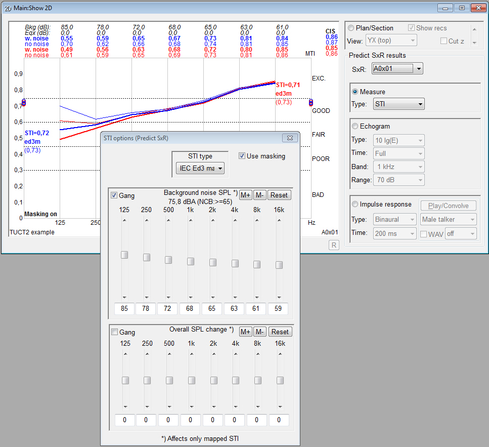
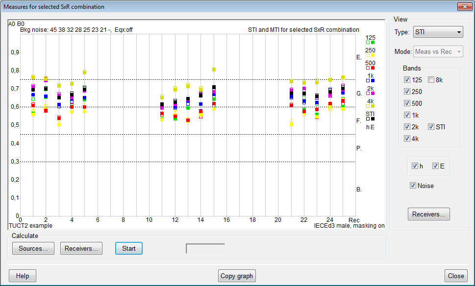
- after a calculation,
the effects on STI when changing
background noise, overall level/eq and
STI type can be studied interactively including the
effect on map statistics, a separately calculated noise
map can be used as background noise. Same Principle
options for U-50 (and with v2 AI
and PI)
- very few result items
have to be decided on before prediction,
old results can be recalled, displayed
and analyzed again in new ways (in most cases also if
new measures or analysis/display features have been
added after the original calculation)
- simple sequence processing
for running several
calculation in sequence
- no use of PLT-files
(in v9 a new PL9-format is used for the main program for geometry/view
check and directivity graphics,
TUCT™ can export to PL9 for presentations
or side by side comparisons).
- several selectable
mapping color palettes.
- flexible structure
for adding future functionality
and measures
Major differences
between TUCT™ v2 and TUCT™ v1:
- the DLL Directivity
Interface (DDI) (SD2-files) for array modeling,
in use since 1998, will no longer be developed but is
replaced by a new and fundamentally improved source and
array handling using a flexible open array text-file format
(CATT-Acoustic Text Array, CTA) that after pre-processing is
saved in a binary format (CATT-Acoustic Binary Array, CBA) used
at actual prediction in TUCT v2. The CTA-format
allows using symbolic numerical and string constants and expressions,
element filters (several formats including encrypted), delays,
polarity reversals, weights and more. A unique and simple way of
modeling line-arrays with high-frequency line wave-guides, or other
line elements, via modular Line ELements (LELs). The CTA-format
can also be used to create incoherent arrays such as for noise line
or array sources.
- a new source-file format using
SOURCE
data blocks to support the new source and array modeling.
To support old projects, that used the DDI, the v9.1
installation will also include the last version of TUCT
v1 (v1.1b) adapted to work with v9.1. Which
TUCT version that will run depends
on the source-file syntax used (SOURCEDEFS => v1,
SOURCE
data blocks => v2).
- electro-acoustic source IRs are
now re input voltage (i.e. not re 1 m on axis but re input) so it includes
the loudspeaker Sensitivity. Input can be set as voltage (dBV) or
acoustic SPL + microphone Sensitivity.
- when using natural sources,
such as an ideal omni for basic room acoustics, it only
requires adapting to the new source format syntax that for
natural sources is straightforward (via a direct conversion
option) and all the added functionality and improvements
with TUCT v2 will be available
- when using electro-acoustic
sources and arrays the new syntax is more involved since it also means
a paradigm shift especially regarding arrays but will
give many benefits for sound-system predictions in addition
to also be able to use the many TUCT
v2 additions. A basic direct conversion is included.
- use of a cockie-cut sector directivity
.SDX as a replacement of the DLL interface SECTOR0 SD2 that required
using TUCT1.
- air absorption uses a distance-dependent
filter for direct sound and 1st order specular instead
of only octave-band values
- Map direct,
Rendering, Map measures and Predict
SxR are based on direct sound and 1st order impulse
responses and not only octave-band data.
- Both E and h include
direct sound, 1st order specular and diffraction
(if on) interference.
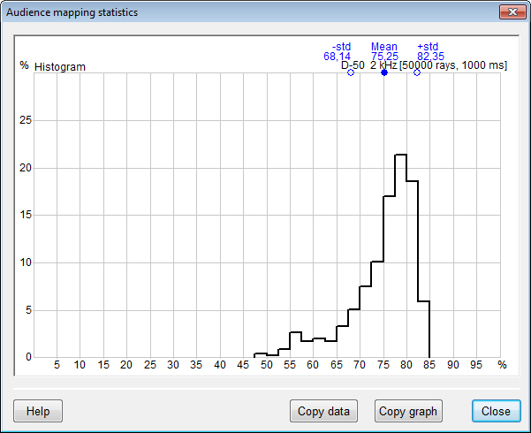
- an audience area mapping result
display option to view a subset of audience plane map
results for which Statistics is calculated
- import of prediction settings
from other projects
- sources are defined as either
coherent (typically loudspeakers) or inchoerent
(typically natural sources) where incoherent sources will not
interfere.
- further added or updated measures from ISO 3382-1:2009
- Articulation Index (AI) and
Privacy Index (PI) based on ASTM E1130-08
- for all EDT, T-15, T-20 and
T-30 predictions it is ensured that the echogram/IR length
is sufficient to estimate valdid decays
- the new flexible Show
Graphs displays selected measures as function
of receiver id, distance from source (r or log2(r)) for
any combination of sources and receivers, octave-bands, A-weighted
and linear, E and h.
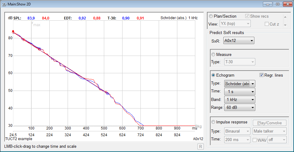
- C-7, T-15 and T-20 implemented
also for audience mapping and are display options for
audience mapping mouse-over Echogram that now shows the full
length (instead of the early part only) with Schröder
integration and optional EDT, T-15, T-20 or T-30 values
and line regression, graphics and data export
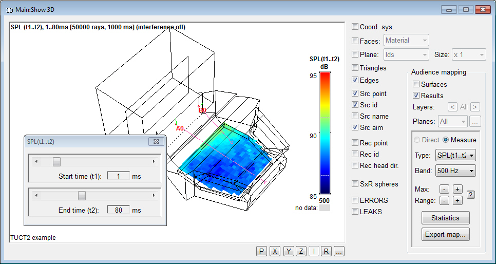
- a new Map
measures option SPL(t1..t2) where the direct and pseudo-direct
sound (such as a stage floor reflection) can be excluded
and only up to a selected upper time can be included, e.g.
1..50 ms or 5..80 ms
- the Src aim
option displays long aim lines (intersecting the closest surface)
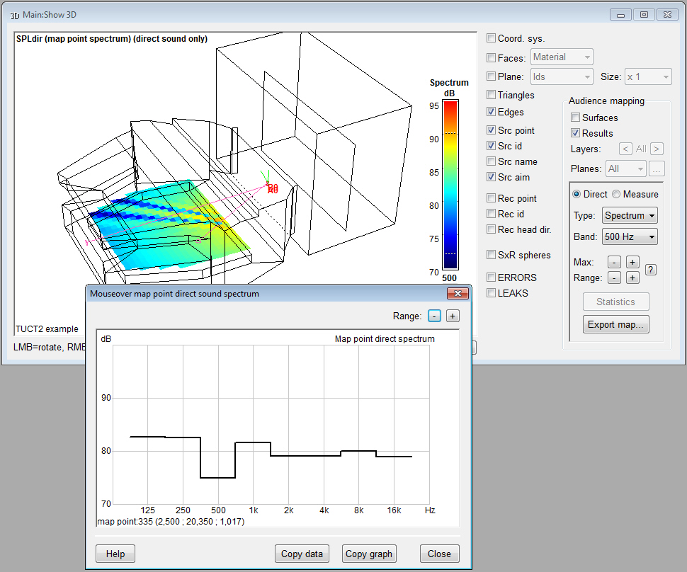
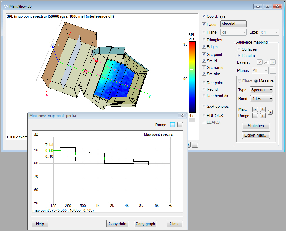
- Pixel Rendering
shows mouse-over SPL spectra, calculates all bands directly and rescaling
the map does not require a recalculation
- Surface Rendering
shows mouse-over SPL spectra and calculates all bands
directly.
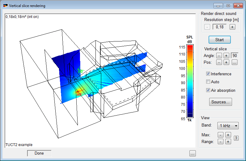
- the new Vertical
Slice Rendering maps the direct SPL across
a moveable vertical surface to e.g. show vertical array
coverage
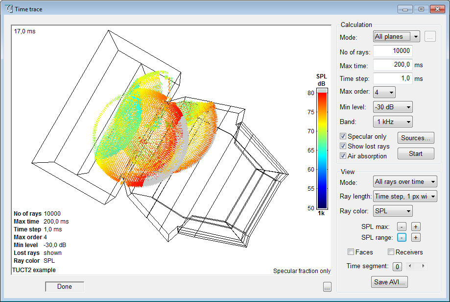
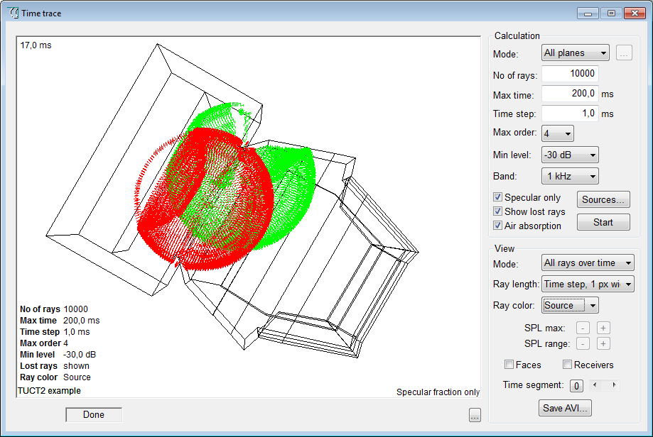
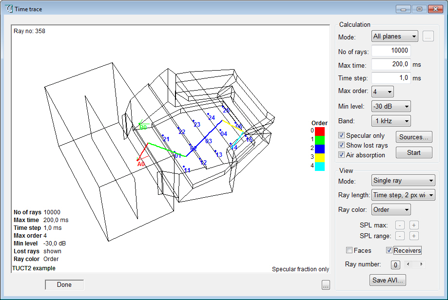
- Time Trace options
for reflector coverage and to show one ray at a time.
- Image Source Model
option to only show reflections above a certain SPL threshold
- for a fuller summary
of all additions and changes in v9.1/TUCT
v2 see here.
Licensing:
- for v8 and v9.0 users
v9.1 is treated as an update and
as v8 has separate Prediction
(with demo auralization) and Full auralization
versions
|